



 By Tech Warmup
If you are new to electronics, working with a breadboard is one of the best ways to begin building circuits without any soldering. In this beginner-friendly project, we will create a simple control system where four push buttons independently control four LEDs. This activity introduces basic components, wiring techniques, and the fundamental concept of digital input and output.
What You Will Learn
- Understanding the use of a breadboard for prototyping
- Working with push buttons as input devices
- Controlling LEDs using simple circuits
- Basics of current-limiting resistors and power connections
Components Required
|
|

Circuit Idea
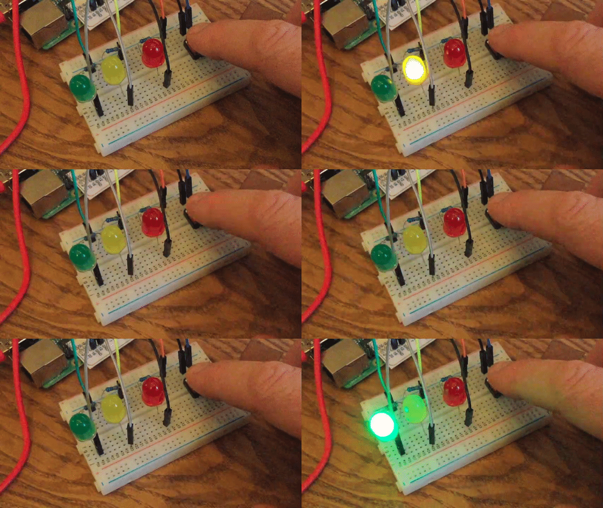
Each push button is connected as a manual switch. When the button is pressed, current flows through an LED, causing it to light up. When released, the LED turns off. This is one of the simplest examples of how input devices can directly control output components.
To ensure the LEDs are protected, a resistor is used in series with each LED. The breadboard helps us connect everything neatly and allows easy fixes if something does not work correctly.
Wiring Steps
- Place the four LEDs in separate rows on the breadboard. Connect the negative leg (cathode) of every LED to the ground (GND) rail of the breadboard.

- Connect a resistor to the positive leg (anode) of each LED.

- Connect the other end of each resistor to the output side of the push button.

- Connect the input side of the push buttons to the 5V power source.

- Finally, power the ground and 5V rails properly from your power supply.

- After the power connection press the push button one after another .


Once completed, pressing each button will turn on its corresponding LED. You now have a working input-to-output circuit.
Why This Project Matters
This hands-on practice builds confidence in handling basic components and understanding how an action (button press) creates a response (LED light). Projects like this form the foundation for future development in embedded systems, automation, robotics, and more advanced electronics.
Next Steps
After completing this project successfully, you can expand the idea by:
- Adding more LEDs and switches
- Creating different lighting patterns
- Connecting the buttons to a microcontroller like Arduino to add logic
Conclusion
This simple breadboard project demonstrates fundamental electronics principles in a practical and interactive way. Whether you are a student, hobbyist, or someone curious about electronics, this activity is an excellent starting point for learning how circuits work.
By Tech Warmup
If you are new to electronics, working with a breadboard is one of the best ways to begin building circuits without any soldering. In this beginner-friendly project, we will create a simple control system where four push buttons independently control four LEDs. This activity introduces basic components, wiring techniques, and the fundamental concept of digital input and output.
What You Will Learn
- Understanding the use of a breadboard for prototyping
- Working with push buttons as input devices
- Controlling LEDs using simple circuits
- Basics of current-limiting resistors and power connections
Components Required
|
|
Circuit Idea
Each push button is connected as a manual switch. When the button is pressed, current flows through an LED, causing it to light up. When released, the LED turns off. This is one of the simplest examples of how input devices can directly control output components.
To ensure the LEDs are protected, a resistor is used in series with each LED. The breadboard helps us connect everything neatly and allows easy fixes if something does not work correctly.
Wiring Steps
- Place the four LEDs in separate rows on the breadboard. Connect the negative leg (cathode) of every LED to the ground (GND) rail of the breadboard.
- Connect a resistor to the positive leg (anode) of each LED.
- Connect the other end of each resistor to the output side of the push button.
- Connect the input side of the push buttons to the 5V power source.
- Finally, power the ground and 5V rails properly from your power supply.
- After the power connection press the push button one after another .
Once completed, pressing each button will turn on its corresponding LED. You now have a working input-to-output circuit.
Why This Project Matters
This hands-on practice builds confidence in handling basic components and understanding how an action (button press) creates a response (LED light). Projects like this form the foundation for future development in embedded systems, automation, robotics, and more advanced electronics.
Next Steps
After completing this project successfully, you can expand the idea by:
- Adding more LEDs and switches
- Creating different lighting patterns
- Connecting the buttons to a microcontroller like Arduino to add logic
Conclusion
This simple breadboard project demonstrates fundamental electronics principles in a practical and interactive way. Whether you are a student, hobbyist, or someone curious about electronics, this activity is an excellent starting point for learning how circuits work.
Comments