


 By Tech Warmup

Introduction to Multimeter
A multimeter is an electronic measuring instrument used to test and measure different electrical quantities in a circuit.
It is one of the most important tools for electricians, technicians, and engineers.
Functions of a Multimeter:
-
Measure Voltage (V): To check how much voltage a battery or circuit has.
-
Measure Current (A): To see how much current is flowing.
-
Measure Resistance (Ω): To test how much opposition a component gives to current.
-
Continuity Test: To check if a wire or circuit is complete (shows beep sound if connected).
How to Measure Voltage
Measurment of Volatge requires few steps . Follow the steps to measure the voltage in a DC source and AC source .
Step 1: Connect the Test Leads
-
Insert the black lead into the port marked COM (common).
-
Insert the red lead into the port marked V (voltage).
-
Remember: black = negative, red = positive.

Step 2: Select Voltage Mode
-
Rotate the dial to the correct voltage setting.
-
V~ → for AC voltage (home outlets, lights, appliances).
-
V⎓ → for DC voltage (batteries, car circuits, electronics).
-
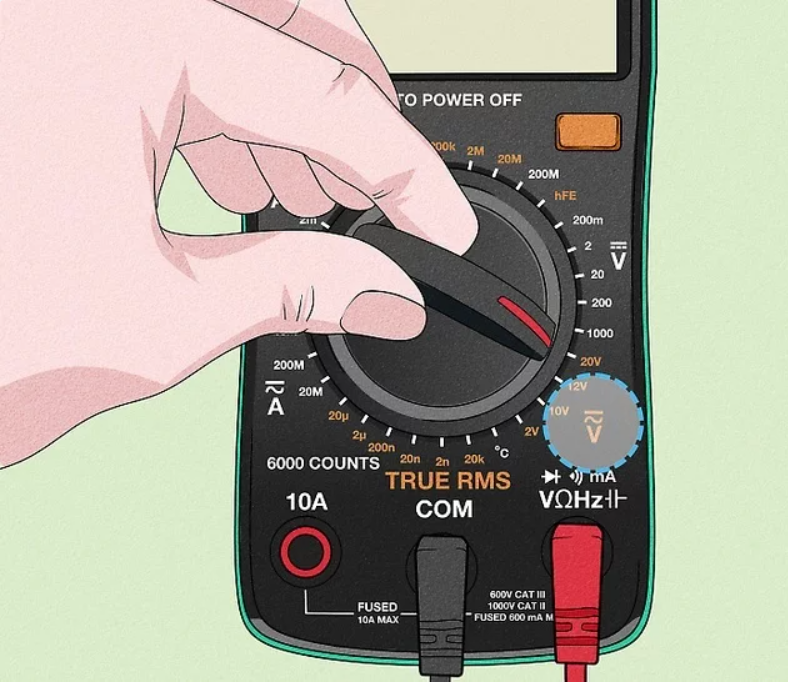
Step 3: Choose Voltage Range
-
If your multimeter has auto-range, just leave it on.
-
If not, set the range slightly higher than the expected value.
-
Example: Measuring a 12V battery → set dial to 20V, not 2V.
-
-
If unsure, start with the highest setting.

Step 4: Place the Probes
-
Touch the black probe to the negative terminal (or neutral/ground).
-
Touch the red probe to the positive terminal (or live wire).
-
⚠️ Safety tips:
-
Hold probes by their insulated handles.
-
Don’t let probe tips touch each other.
-
Keep fingers away from metal ends.
-

Step 5: Read the Display
-
The screen shows the measured voltage.
-
Compare with expected values:
-
A wall outlet should read ~120V (or 240V for larger appliances).
-
A new 12V battery should be close to 12V; much lower means weak or dead.
-

How to Measure Current Using a Multimeter
Step 1: Connect the Test Leads
-
Insert the black lead into the COM port.
-
Insert the red lead into the A (amps) or mA (milliamps) port depending on the expected current.
-
Turn the dial to the Amps (A or mA) setting.
-
Amperage shows how many electrons flow through a circuit, similar to how the size of a water hose controls water flow.

Step 2: Open the Circuit
-
Disconnect one wire in the circuit.
-
This allows your multimeter to act as an ammeter, completing the circuit and measuring the current.
-
It doesn’t matter which side of the wire you disconnect.

Step 3: Connect Multimeter and Read Current
-
Touch the multimeter probes to the free terminals where the wire was removed.
-
Read the current value on the multimeter screen.
-
If reading is very low, switch to mA for more accuracy.
-
You can also test different sections of a circuit to check for faulty wires.

Measuring Resistance
Step 1: Connect Test Leads
-
Insert the black lead into COM.
-
Insert the red lead into the Ω terminal.
-
Ω (ohms) is the unit of resistance. Resistance shows how much a material opposes the flow of electricity.

Step 2: Set the Dial
-
Turn the dial to the Ω symbol.
-
Choose a number close to the expected resistance. If unsure, start with the highest setting.

Step 3: Measure the Component
-
Place the probes on each end of the resistor or component.
-
Read the resistance on the multimeter screen.
-
Adjust the dial for more precise reading if needed.

Testing Continuity
Step 1: Power Off
-
Unplug the device or remove batteries.
-
Continuity cannot be tested if the device has power.

Step 2: Connect Leads and Set Dial
-
Insert the red lead into V, Ω, or continuity terminal.
-
Insert the black lead into COM.
-
Turn the dial to the continuity symbol (looks like a sound wave).

Step 3: Test the Component
-
Place black probe on one end and red probe on the other.
-
Both probes must touch simultaneously.
-
Can test wires, switches, fuses, or conductors.
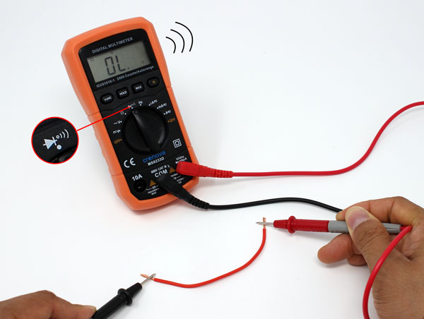
Step 4: Listen for Beep
-
A beep means good continuity (low resistance).
-
No beep indicates broken wire or high resistance.
By Tech Warmup
Introduction to Multimeter
A multimeter is an electronic measuring instrument used to test and measure different electrical quantities in a circuit.
It is one of the most important tools for electricians, technicians, and engineers.
Functions of a Multimeter:
-
Measure Voltage (V): To check how much voltage a battery or circuit has.
-
Measure Current (A): To see how much current is flowing.
-
Measure Resistance (Ω): To test how much opposition a component gives to current.
-
Continuity Test: To check if a wire or circuit is complete (shows beep sound if connected).
How to Measure Voltage
Measurment of Volatge requires few steps . Follow the steps to measure the voltage in a DC source and AC source .
Step 1: Connect the Test Leads
-
Insert the black lead into the port marked COM (common).
-
Insert the red lead into the port marked V (voltage).
-
Remember: black = negative, red = positive.
Step 2: Select Voltage Mode
-
Rotate the dial to the correct voltage setting.
-
V~ → for AC voltage (home outlets, lights, appliances).
-
V⎓ → for DC voltage (batteries, car circuits, electronics).
-
Step 3: Choose Voltage Range
-
If your multimeter has auto-range, just leave it on.
-
If not, set the range slightly higher than the expected value.
-
Example: Measuring a 12V battery → set dial to 20V, not 2V.
-
-
If unsure, start with the highest setting.
Step 4: Place the Probes
-
Touch the black probe to the negative terminal (or neutral/ground).
-
Touch the red probe to the positive terminal (or live wire).
-
⚠️ Safety tips:
-
Hold probes by their insulated handles.
-
Don’t let probe tips touch each other.
-
Keep fingers away from metal ends.
-
Step 5: Read the Display
-
The screen shows the measured voltage.
-
Compare with expected values:
-
A wall outlet should read ~120V (or 240V for larger appliances).
-
A new 12V battery should be close to 12V; much lower means weak or dead.
-
How to Measure Current Using a Multimeter
Step 1: Connect the Test Leads
-
Insert the black lead into the COM port.
-
Insert the red lead into the A (amps) or mA (milliamps) port depending on the expected current.
-
Turn the dial to the Amps (A or mA) setting.
-
Amperage shows how many electrons flow through a circuit, similar to how the size of a water hose controls water flow.
Step 2: Open the Circuit
-
Disconnect one wire in the circuit.
-
This allows your multimeter to act as an ammeter, completing the circuit and measuring the current.
-
It doesn’t matter which side of the wire you disconnect.
Step 3: Connect Multimeter and Read Current
-
Touch the multimeter probes to the free terminals where the wire was removed.
-
Read the current value on the multimeter screen.
-
If reading is very low, switch to mA for more accuracy.
-
You can also test different sections of a circuit to check for faulty wires.
Measuring Resistance
Step 1: Connect Test Leads
-
Insert the black lead into COM.
-
Insert the red lead into the Ω terminal.
-
Ω (ohms) is the unit of resistance. Resistance shows how much a material opposes the flow of electricity.
Step 2: Set the Dial
-
Turn the dial to the Ω symbol.
-
Choose a number close to the expected resistance. If unsure, start with the highest setting.
Step 3: Measure the Component
-
Place the probes on each end of the resistor or component.
-
Read the resistance on the multimeter screen.
-
Adjust the dial for more precise reading if needed.
Testing Continuity
Step 1: Power Off
-
Unplug the device or remove batteries.
-
Continuity cannot be tested if the device has power.
Step 2: Connect Leads and Set Dial
-
Insert the red lead into V, Ω, or continuity terminal.
-
Insert the black lead into COM.
-
Turn the dial to the continuity symbol (looks like a sound wave).
Step 3: Test the Component
-
Place black probe on one end and red probe on the other.
-
Both probes must touch simultaneously.
-
Can test wires, switches, fuses, or conductors.
Step 4: Listen for Beep
-
A beep means good continuity (low resistance).
-
No beep indicates broken wire or high resistance.